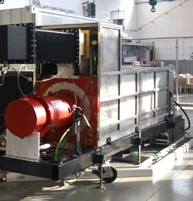
Amplifiers
The amplifier choice for each RF system is essential due to it is a key component in the accelerator operation in and a significant fraction of total cost of the RF chain. The amplifier also is the source of failure; therefore, a careful availability consideration and constant effort of maintenance are required. The technology of the amplifier chosen for each type of accelerating structure depends on study of the next factors: the frequency range, the peak power capability as well as the average power capability in case of CW accelerators, the gain, the phase stability and finally the simplicity, availability and long life.

Two types of amplifiers are required for the NC section:
Notice: Trying to access array offset on value of type bool in /home/essbilbao/public_html/wp-content/plugins/vc-extensions-bundle/cubebox/vc-extensions-cubebox.php on line 891
Klystrons
The klystron is an amplifier that has been used extensively for accelerators for many years at MW-level.
They amplify a lower level RF signal to the power level needed for each cavity, which is feed to the RF distribution system and transmitted up to the RFQ and DTL tanks.
In a klystron the electrons in an electron beam are velocity-modulated by a low-level signal by passing through several cavities the electrons are velocity modulated and bunched to provide an amplified signal.
Klystrons offer very high power – up to several MW using multi-beam devices, extremely high gain up to 50 dB and an efficiency up to around 65% at maximum power (basically a class A) with pulsed HV (that powers the electron gun and hence the electron beam).
The main specifications of the klystrons are:
- Nominal output peak power ≥ 2.9 MW.
- Central frequency 352.21 MHz.
- Bandwidth ≥ +/- 1 MHz.
- High voltage pulse width ≤ 4 ms.
- RF pulse width ≤ 3.5 ms.
- RF Pulse repetition rate ≤ 14 Hz.
- VSWR ≤ 1.2
Three klystrons were manufactured by CPI and other new three klystrons are in the call for tender process.

Klystron interfaces
Klystron Driver
Solid State Power Amplifiers
The ESS accelerator MEBT section includes 3 buncher cavities working at 352.21 MHz that should be fed by three medium power pulsed RF solid-state amplifiers. Each amplifier shall provide some 20kW at the cavity coupler, however the amplifier peak output RF power will need to be higher taking into account transmission line losses, margin for overhead and RF regulation. Therefore each SSPA transmitter is expected to deliver 30kW peak output power at its output. These amplifiers are based on solid-state technology that offers several advantages in comparison with tube-based amplifiers, such as: better reliability and lifetime, modular structure, low voltage power supplies and no vacuum complications.
The main specifications are:
- Center Frequency 352.21 MHz.
- Bandwidth @-1dB ≥ ± 5 MHz.
- Output nominal peak power ≥ 30 kW.
- Gain (nominal output power) ≥ 75 dB.
- Input/ output impedance 50 ohm.
- Input/ output VSWR ≤ 1.2:1.
- Noise figure ≤ 10 dB.
- RF pulse width ≤ 3.5 ms.
- RF pulse repetition rate ≤ 14 Hz.
- Power consumption ≤ 6 kW.
A public call for tender for design and manufacturing of three 30kW solid-state amplifiers was launched and the contract awarded to BTESA Broad Telecom S.L. after precise evaluation of offers from several bidders.
Notice: Trying to access array offset on value of type bool in /home/essbilbao/public_html/wp-content/plugins/vc-extensions-bundle/cubebox/vc-extensions-cubebox.php on line 891
Solid State Power Amplifiers
Notice: Trying to access array offset on value of type bool in /home/essbilbao/public_html/wp-content/plugins/vc-extensions-bundle/cubebox/vc-extensions-cubebox.php on line 891
2kW SSPA test
Notice: Trying to access array offset on value of type bool in /home/essbilbao/public_html/wp-content/plugins/vc-extensions-bundle/cubebox/vc-extensions-cubebox.php on line 891


