RF systems
ESS will be the world’s most powerful pulsed neutron source based on a linear pulse accelerator (Linac) which accelerates a proton beam of 62.5 mA current to an energy peak of 2000 MeV.
The ESS linac includes a normal conducting or warm linac section composed of an Ion Source, a RFQ (Radio Frequency Quadrupole), a MEBT (medium Energy Beam Transport) with three bunchers cavities type, and DTL (Drift Tube Linac) consisting of 5 tanks. Then, the superconducting section start with the spokes cavities to continue with medium and high beta cavities.

The normal conducting linac will be powered by nine RF power sources operating at 352.21 MHz. The RF system can be defined as all the components and subsystems needed to generate and deliver RF power to the cavities between the wall power plug (AC power from the grid) and the cavity power coupler (at the cavity input). The complete chain includes pulsed high voltage sources (or modulators), high power amplifiers, waveguide or coaxial RF distribution systems and Low Level RF control systems (LLRF).
ESS Bilbao’s tasks included the design and prototyping, procurement, integration, factory testing, transportation, delivery and finally the supervision of the installation and assistance with the commissioning of the RF stations at the ESS site in Lund (Sweden).
RF Systems layout
(ESS´s courtesy)RF Systems layout
(ESS´s courtesy)
GOALS
1.
The RF systems generate the required RF power to accelerate the particles correctly.
2.
The RF systems have to maintain the amplitude and phase of the accelerating field within a given tolerance to accelerate the charged particle beam.
3.
The RF systems protect the cavity and all their own components from any failure.

SCOPE
ESS Bilbao is in charge of the “RF systems for warm linac” work package including the design, prototyping, procurement, as well as installation (TBC) and testing at the ESS site of the nine RF power source for the RFQ, 3 MEBT bunchers and 5 DTL tanks.
As the superconducting spoke cavities also operates at the same frequency as the normal conducting linac, the ESS Bilbao´s in-kind contribution also includes the LLRF systems for the superconducting spoke linac (26 cavities).
The NC RF system work package include the next deliveries:
- Three modulators (660 kVA).
- Six high power amplifiers: klystrons (2.9 MW).
- Six klystron drivers (500 W).
- Three solid state power amplifiers (30k W; including circulator and load).
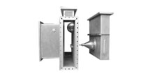
- Six RF distribution chains (WR2300).
- Three RF distribution chains (rigid EIA 1 5-8”).
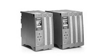
- Nine slow and fast local protection systems.
- Nine LLRF systems for NC + 26 LLRF systems for SC spoke section.
- Ten LO boxes.
CAPACITY AND DEVELOPMENT
Simulation and Modelling
RF passive components are designed by means of 3-D full-wave electromagnetic field software Ansys HFSS and accurate models are created and simulated with Comsol Multiphysics.
Altium Designer provides the capability the powerful tool to design the electronic required for the RF applications.
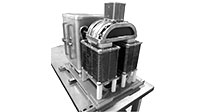
Magic T
Cavity simulations
Cavity Layout
Experimental characterization
High-quality RF instrumentation is available to implement specific test-bench for the RF passive or active components or subsystems operating in CW or pulse mode.
Test bench
RF measurements
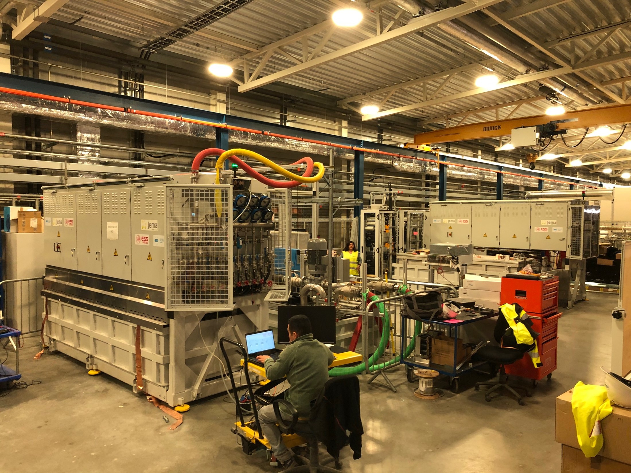
High Power RF Conditioning
The three buncher cavities, along with their power cou- plers, have been RF conditioned at ESS Bilbao’s premi- ses. This process implied a progressive increase of pul- se length, repetition rate and power until the nominal operating conditions were reached, while maintaining high vacuum levels. Completion of that process for the cavities meant a huge milestone for ESS Bilbao, for the sake of validating the design, reducing risks and shor- ten commissioning time at ESS
Buncher cavities installation
Characterization buncher cavities
Control design
Remote control of instrumentation, automatization of procedures or processes, integration of state machines or developments of graphical user interfaces are implemented inside the RF control design.